

Tolerances are where fabrication cost actually lives. Material choices matter, volumes matter, and finish requirements matter—but few elements on a fabrication drawing affect cost as quickly as the tolerance block. Few also create more avoidable expense than tolerances specified out of habit rather than function. Engineers who understand how sheet metal tolerances work—what is achievable by default, what tightening actually costs, and where precision genuinely matters—consistently get better parts for less money.
This guide covers the tolerance standards that apply to precision sheet metal fabrication, the cost mechanics behind them, and how to specify tolerances that protect part function without paying for precision the part does not need.
Sheet Metal Is Not Machining
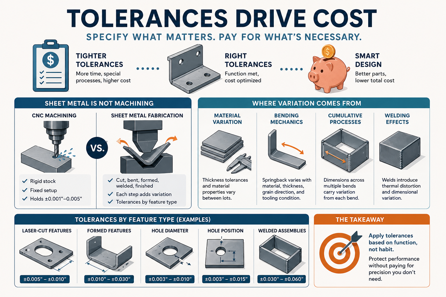
The most common tolerance mistake starts with a reasonable instinct: applying machining expectations to sheet metal parts. CNC machining routinely holds ±0.001″–0.005″ because it cuts features into rigid stock in a fixed setup. Sheet metal fabrication follows a fundamentally different process chain. Flat material is cut, then bent, formed, welded, and finished, and each stage introduces its own variation.
- Material variation: Sheet stock carries thickness tolerances from the mill, and mechanical properties vary slightly between lots. Those differences affect how the material bends.
- Bending mechanics: Every bend involves springback, or the material’s partial return toward flat after forming. Springback varies with material type, grain direction, thickness, and tooling condition. Formed dimensions should not be expected to hold the same tolerances as cut features through bending alone, regardless of press brake capability.
- Cumulative processes: A dimension that crosses two bends carries the variation of both bends plus flat-pattern accuracy. A dimension measured across a welded joint also carries the effects of thermal distortion.
This is why sheet metal tolerances are specified by feature type rather than as one blanket number. A title-block tolerance of ±0.005″ across an entire formed sheet metal part is likely to produce either a no-quote or a very expensive conversation.
Typical Tolerances by Feature Type
Achievable tolerances depend on material, thickness, part geometry, and equipment, but well-equipped precision fabricators generally begin within these ranges:
| Feature type | Typical starting range | Main source of variation |
|---|---|---|
| Laser-cut holes, edges, and cutouts | ±0.005″–0.010″ | Cutting process, material, gauge |
| Formed dimensions and flange lengths | ±0.010″–0.030″ | Springback, tooling, bend count |
| Bend angles | Approximately ±1° | Material, tooling, springback |
| Across-bend dimensions | Project-specific; wider than same-plane features | Accumulated bend variation |
| Weldments and assemblies | Project-specific | Heat distortion, fit-up, stack-up |
| Flatness on large thin panels | Project-specific | Material condition and geometry |
Hole-to-hole dimensions on the same plane are generally the most accurate dimensions on a sheet metal part, and modern fiber lasers can reliably hold the tight end of the cut-feature range on common gauges. Every bend a dimension crosses adds variation, which is why across-bend dimensions require wider tolerances. When hole position is critical, dimensioning from a same-plane feature usually gives the fabricator a more stable reference.
Critical assembly dimensions are often controlled with fixtures, but the better design is one that avoids making unnecessary dimensions critical in the first place. Flatness callouts on large, thin panels present a similar problem because they work against the material’s natural behavior. Specify flatness only where function requires it and expect the requirement to influence both process and price.
The EVS tolerance chart provides the default ranges our quoting and engineering teams use for common processes and feature types.
Which Standards Apply to Sheet Metal Tolerances?
General tolerance standards create a shared baseline when a drawing does not assign an individual tolerance to every dimension. They do not, however, replace agreement with the fabricator about what a particular geometry and process can hold economically.
ISO 2768 is commonly used on international drawings to define general tolerances for linear and angular dimensions that are not individually toleranced. In the United States, ASME Y14.5 provides the primary framework for geometric dimensioning and tolerancing, including datum systems, position, profile, orientation, and form controls. The drawing should identify the governing standard and edition rather than assuming every supplier interprets “standard tolerances” the same way. Even when a recognized standard applies, formed dimensions, welded assemblies, cosmetic surfaces, and other process-sensitive features may still need project-specific tolerances established during quoting.
 Standard vs. Precision: The Tolerance Tiers
 Standard vs. Precision: The Tolerance Tiers
Fabrication work broadly falls into several capability tiers. Identifying which tier the part actually needs is one of the first cost decisions in the design process.
- General or structural fabrication: Tolerances in the ±1/16″–1/8″ range for frames, brackets, architectural components, and structural work where fit is relatively forgiving.
- Standard sheet metal fabrication: Roughly ±1/32″–1/16″ on formed dimensions for enclosures, panels, guards, and the broad middle of industrial sheet metal parts.
- Precision sheet metal fabrication: Tighter control on selected critical features, often including ±0.005″–0.010″ cut-feature requirements, closely controlled hole patterns, mating interfaces, and other function-critical dimensions. Electronics enclosures, medical and aerospace components, EMI or environmental sealing applications, and hardware-dense designs often fall into this category. Formed and assembled dimensions still require process-appropriate tolerances.
These tiers describe capability classes, not quality grades. A structural bracket made to precision tolerances is not necessarily a better bracket; it is simply a more expensive one.
Tolerance strategy becomes especially important in data center racks, enclosures, panels, and related infrastructure components. Hole-pattern alignment, hardware placement, assembly fit, and door or panel interfaces may all be critical, while many other dimensions can remain at standard fabrication tolerances.
The difference between standard and precision sheet metal fabrication is therefore not that every dimension becomes tighter. It is that selected features receive the equipment, process control, and inspection appropriate to their function.
What Tight Tolerances Actually Cost
Tolerance cost is not an arbitrary surcharge. Tightening a requirement changes the process, and the effects compound.
- Slower processing: Holding tighter dimensions may require slower cutting parameters, more careful setups, more frequent tool and die verification, or different equipment altogether.
- Inspection burden: Every tightened dimension becomes a dimension someone must measure, either on every part or according to a defined sampling plan. That work requires calibrated equipment, inspection time, and documentation.
- Scrap and rework: Narrower tolerance windows reject more parts. A requirement near the edge of process capability turns normal process variation into scrap.
- Tooling and fixturing: Critical formed or assembly dimensions may require dedicated fixtures, custom tooling, or additional operations such as machining after forming.
That compounding effect is why tolerance rationalization can reduce cost so substantially. Tightening only the dimensions that protect function and relaxing the rest can lower fabrication cost by 15–30% on tolerance-dense designs before any other design change is made.
Tolerance strategy is also one of the largest cost levers engineers can address before first article, when changes are still relatively inexpensive and do not require rework, revised tooling, or production delays.
A Case Study in Over-Tolerancing
One representative enclosure design arrived with ±0.002″ specified on formed flange dimensions—a machining tolerance applied to a bent sheet metal feature. The requirement could not be achieved reliably through forming alone. Meeting it as drawn would have required secondary machining after forming, adding another operation and materially increasing part cost.
The flange’s actual function was to mount a gasketed cover, and the design worked correctly at ±0.015″. The solution was not more sophisticated fabrication. It was a short conversation about what the part actually needed, followed by a revised drawing. This type of mismatch is one of the recurring challenges in metal fabrication: tolerances carried over from a CAD template, inherited from a machined version of the part, or tightened simply out of caution. It is also one of the least expensive problems to solve, provided it is identified during quoting rather than after first article.
Consumer-facing products raise the stakes further — kiosk enclosure fabrication is a case study in specifying tight tolerances where components mate and relaxing them everywhere else.
GD&T in Sheet Metal: Use It Where It Earns Its Place
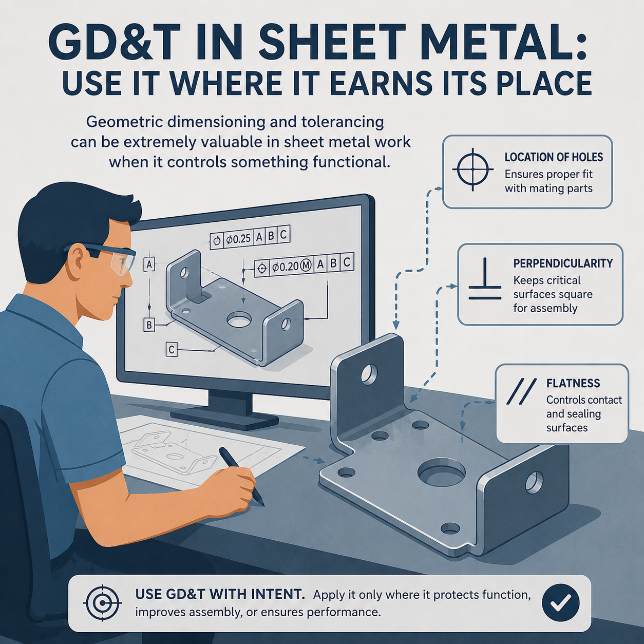 Geometric dimensioning and tolerancing can be extremely valuable in sheet metal work when it controls something functional.
- Datum strategy matters most. Choose datums that reflect how the part is fixtured, formed, and used. A datum scheme based on the mounting surface and locating holes gives the fabricator a stable measurement framework. A datum based on a formed edge introduces bend variation into every measurement taken from it.
- Position tolerances on hole patterns are among the highest-value GD&T applications in sheet metal, particularly for same-plane connector, mounting, and hardware patterns. Position controls what actually matters—whether the pattern fits—while often allowing more manufacturing freedom than coordinate tolerances.
- Profile tolerances work well for controlling formed contours where a blanket linear tolerance would either over-constrain or under-constrain the geometry.
- Exotic controls should be used selectively. Every GD&T frame creates an inspection obligation. Frames that do not protect function add cost without adding value.
Tolerance strategy belongs within the broader design-for-manufacturability review, alongside bend design, material selection, hardware placement, welding, and assembly requirements. That is where most of the cost-saving opportunities are found.
How to Specify Tolerances: A Practical Approach
- Separate critical from conventional. Identify the dimensions that govern function, including mating interfaces, hole patterns, sealing surfaces, and required clearances. Tolerance those deliberately. Allow the standard title-block tolerance to govern everything else.
- Match the tolerance to the feature type. Cut features can carry the tightest requirements. Formed dimensions need realistic bending windows. Across-bend and assembly dimensions generally need wider tolerances.
- Dimension from function. Locate critical holes from same-plane references rather than across bends whenever possible. Choose datums that reflect how the part will be fixtured and used.
- Put the numbers on the drawing. “Standard tolerances apply” can mean different things at different shops. A tolerance block organized by feature type—cut, formed, and angular—removes the ambiguity that leads to padded quotes and first-article surprises.
- Flag critical dimensions in the RFQ. Telling the fabricator which dimensions matter and why makes it easier to recommend processes that protect function at a lower cost. A solid model paired with a PDF drawing that clearly marks critical dimensions is also the kind of complete package that produces faster, more accurate quotes. These drawing and tolerance details belong among the questions procurement should address during a fabrication RFQ.
- Ask before tightening. When a dimension appears to require more than the standard process range, raise it during quoting. Sometimes the answer is a different process. More often, a small design adjustment can eliminate the need for the tighter requirement.
How Tolerances Are Verified: Measurement and Quality Systems
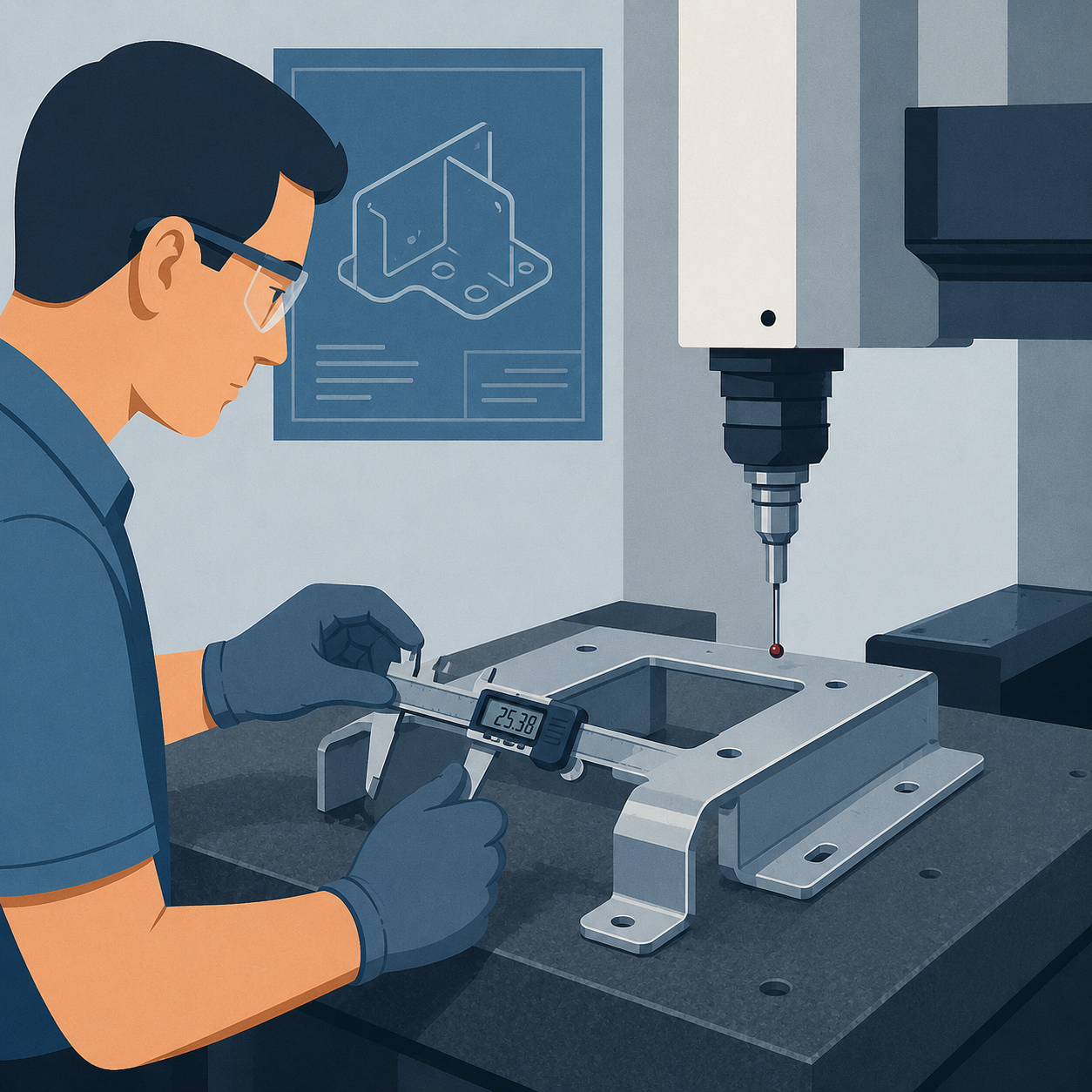
A tolerance is only as meaningful as the measurement behind it. Precision fabrication requires metrology matched to the tolerances being claimed and process discipline that catches drift before it becomes scrap. At EVS, dimensional verification uses equipment including a ROMER Absolute Arm portable CMM for complex and formed geometries, coordinate measuring machines for critical-feature verification, and FabriVISION laser scanning for rapid first-article and flat-pattern inspection.
That equipment operates within EVS’s ISO 9001:2015-certified quality system and documented inspection processes. Combined with engineering review during quoting, this is what turns a precision tolerance from an aspiration into a measurable production commitment.
The Bottom Line
Sheet metal tolerances are a design language. They tell the fabricator what matters. Drawings that communicate that clearly—with realistic feature-specific tolerances, deliberately chosen critical dimensions, and functional datums—are quoted faster, cost less, and move through first article with fewer surprises. Drawings that do not communicate it clearly tend to produce padded quotes at best and expensive redesign or rework at worst.
Have a design ready for tolerance review? Request a quote, and our engineering team will review your drawings—including tolerance strategy—before anything is cut. You can also call (973) 839-4432 to discuss your project.
Frequently Asked Questions About Sheet Metal Fabrication Tolerances
What are typical tolerances for sheet metal fabrication? Typical defaults are ±0.005″–0.010″ for laser-cut features, ±0.010″–0.030″ for formed dimensions depending on material and bend count, and approximately ±1° for bend angles. Assemblies and weldments generally carry wider tolerances because of welding distortion and part-to-part stack-up. Exact requirements should be agreed upon with the fabricator during quoting.
Why can’t formed features hold the same tolerances as cut features? Bending introduces springback, which varies with material properties, thickness, grain direction, and tooling condition. Cut features are produced while the material remains flat, while formed dimensions inherit the variation of every bend they cross. Formed tolerances therefore need to be wider than cut-feature tolerances.
Why do tight tolerances increase fabrication cost? Tight tolerances add cost through slower processing, additional inspection, higher scrap rates, and sometimes dedicated tooling or secondary operations. Rationalizing tolerances by tightening only functionally critical dimensions can substantially reduce fabrication cost and may lower cost by 15–30% on tolerance-dense designs.
What is tolerance stack-up in sheet metal parts? Tolerance stack-up is the accumulation of individual feature tolerances across a dimension’s path. A dimension that crosses two bends includes the variation of both bends plus flat-pattern accuracy. Stack-up can be reduced by dimensioning critical features from same-plane references and choosing datums that match how the part is fixtured and used.
Should I use GD&T on sheet metal drawings? Yes, where it controls function. Position tolerances on same-plane hole patterns and profile tolerances on formed contours are particularly useful. Datums should reflect real fixturing and use, and GD&T frames that do not protect a functional requirement should be avoided because each one creates an inspection obligation.
How do fabricators verify tight tolerances? Fabricators use metrology matched to the requirement, including coordinate measuring machines, portable CMM arms for formed and complex geometries, and laser scanning for first-article and flat-pattern verification. These tools should operate within a documented quality system that includes calibration, process control, and traceability.
What should I include in an RFQ so tolerances are quoted accurately? Include a solid model and a PDF drawing with a feature-specific tolerance block and clearly identified critical dimensions. Notes explaining the function of those dimensions can also help the fabricator recommend lower-cost processes or design changes while protecting part performance.