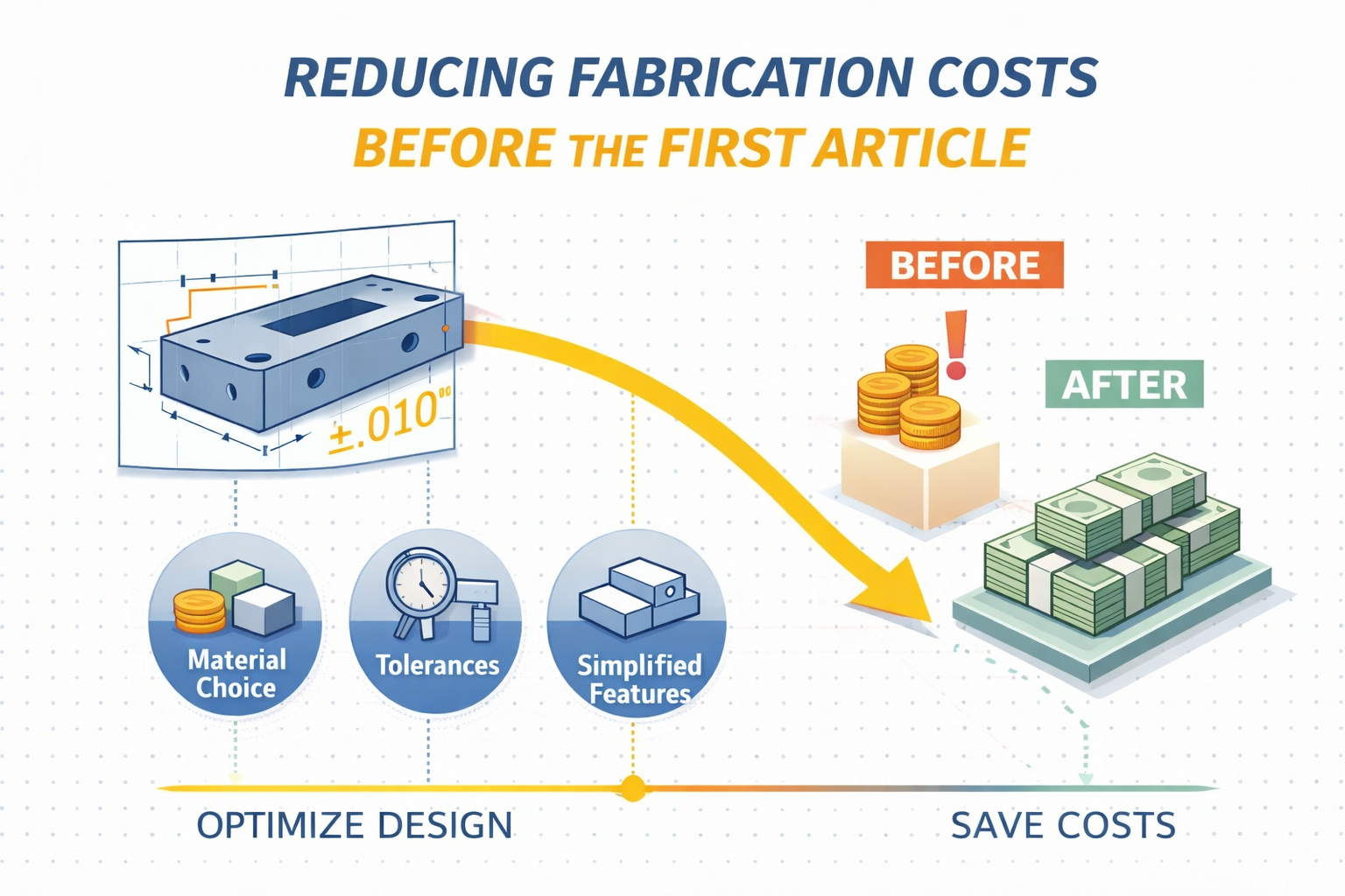
 The most effective time to reduce metal fabrication cost is before the first part is manufactured. Design decisions made during the CAD phase determine 70–80% of a product’s manufacturing cost, yet engineering teams often wait until prototyping or production to discover cost-driving features that could have been optimized months earlier.
This creates a predictable pattern: engineering finalizes a design, procurement solicits quotes, the team discovers fabrication costs exceed budget, and engineering scrambles to make changes under schedule pressure. These late-stage revisions consume engineering time, delay product launch, and often compromise design intent.
The alternative approach involves applying cost-awareness during design development—not after drawings are released. Engineers who understand how design features affect fabrication cost can make informed tradeoffs that reduce manufacturing expense without sacrificing functional requirements.
Why Design Determines Cost
Manufacturing cost is not primarily driven by shop labor rates or material prices. It is driven by the complexity, precision, and processes required to transform raw material into finished parts.
Design features that increase cost:
- Tight tolerances requiring precision equipment or secondary operations
- Complex geometry requiring specialized tooling or manual processes
- Material selections requiring premium stock or extended lead times
- Features that prevent efficient nesting, forming, or welding
- Finishing requirements that add process steps or masking complexity
Design features that reduce cost:
- Standard tolerances achievable with primary manufacturing processes
- Geometry that aligns with equipment capabilities and standard tooling
- Common materials available from distributor stock
- Features designed for manufacturing efficiency
- Finishing specifications that minimize masking and process steps
The difference between a $45 part and a $32 part is rarely the sheet metal itself. It is the design decisions that determine how that sheet metal must be processed. Understanding how design decisions drive cost, lead time, and risk helps engineers make better tradeoffs during the design phase.
Material Selection Impact on Fabrication Cost
Material choice affects more than just material price per pound. It determines what processes are available, what tolerances are achievable, and what lead times are realistic.
Common Material Decisions and Cost Implications
Stainless steel vs. carbon steel:
Stainless costs 2–4x more per pound than carbon steel, but the total cost difference is often greater due to processing factors. Stainless requires different tooling, slower cutting speeds, and specialized welding. For applications where corrosion resistance is required, stainless is necessary. For applications where powder coating provides adequate protection, carbon steel with coating often costs 40–60% less total.
Aluminum alloy selection:
6061-T6 aluminum is widely stocked and readily available. 7075 aluminum offers superior strength but requires special ordering, extended lead times, and premium pricing. For structural applications where 6061 provides adequate strength, specifying 7075 increases cost 30–50% and adds 2–4 weeks lead time.
Thickness standardization:
Sheet metal is stocked in standard gauges. Specifying 0.105″ material when 0.109″ (12 gauge) provides adequate performance forces custom ordering, premium pricing, and extended lead time. Using standard gauges typically available from distributor stock reduces material cost 15–25% and improves lead time predictability.
Material finish specification:
Cold-rolled steel costs less than hot-rolled but requires tighter flatness tolerances from the mill. For parts that will be powder coated, hot-rolled is often adequate and 10–20% less expensive. Understanding which finish requirements are functional vs. preferential reduces material cost without compromising performance.
Cost-Reduction Strategy
Before finalizing material selection, validate:
- Functional requirements: What properties are actually required (strength, corrosion resistance, weight, conductivity)?
- Standard availability: Is the specified material/thickness stocked by distributors?
- Alternative materials: Could a more readily available material meet requirements?
- Total cost impact: How does material choice affect processing, not just material price?
Involve the fabricator’s engineering team during material selection. They can identify equivalent materials that meet functional requirements while improving cost, availability, or manufacturability.
Tolerance Rationalization: Tighter Is Not Always Better
One of the most common cost-driving mistakes in part design is over-specifying tolerances. Engineers often apply tight tolerances by default rather than analyzing which dimensions are functionally critical.
The Cost Impact of Tolerance Specification
Standard tolerances (typically ±0.010″ for cut features, ±0.030″ for formed features, ±1° for bends) are achievable with primary manufacturing processes. Parts with standard tolerances can be produced on standard equipment with normal inspection procedures.
Tight tolerances (±0.005″ or tighter for cut features, ±0.015″ for formed features, ±0.5° for bends) often require:
- Secondary machining operations after primary fabrication
- Fixture-based manufacturing vs. standard tooling
- Coordinate measuring machine (CMM) inspection vs. hand tools
- Process capability studies and statistical process control
- Increased scrap rates and rework frequency
Cost multiplier: Moving from ±0.010″ to ±0.005″ tolerance on critical features can increase part cost 25–40%. Moving to ±0.002″ can double part cost.
Where Tolerances Actually Matter
Not all dimensions require the same precision:
Critical dimensions:
- Hole-to-hole spacing for assembly alignment
- Mounting hole positions interfacing with other components
- Features controlling fit with mating parts
- Dimensions affecting functional performance
Non-critical dimensions:
- Overall part envelope where clearance exists
- Aesthetic features not affecting assembly
- Internal cutouts with adequate clearance
- Bend radii within reasonable range
Tolerance Optimization Process
Review drawings before release and identify:
- Which dimensions directly affect assembly, fit, or function
- Which dimensions have adequate clearance for standard tolerances
- Whether tolerance stackup analysis justifies tight individual tolerances
- If GD&T (Geometric Dimensioning and Tolerancing) could better communicate intent
Often, 80% of dimensions can use standard tolerances while 20% require precision control. Rationalizing tolerances across the design typically reduces fabrication cost 15–30% with no functional compromise.
Design Features That Drive Fabrication Cost
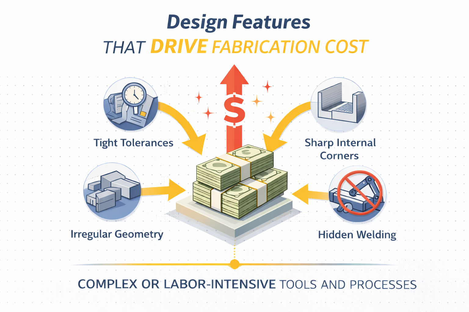 Specific geometric features have predictable cost implications. Understanding these relationships allows engineers to make informed design decisions. Applying design for manufacturability principles during the CAD phase prevents costly late-stage revisions.
Laser Cutting and Punching Considerations
Small holes and narrow slots:
Holes smaller than material thickness or slots narrower than material thickness require slower cutting speeds, increase tool wear, and may require secondary drilling. Minimum recommended: hole diameter ≥ material thickness.
Tight corner radii:
Sharp internal corners require multiple tool passes or secondary operations. Standard laser kerf produces radius approximately equal to material thickness. Tighter radii require secondary machining.
Complex nesting geometry:
Parts with irregular shapes, large voids, or inefficient geometry waste material. Rectangular or regular geometric shapes maximize material utilization. Material waste directly affects part cost.
Tight edge-to-feature spacing:
Features positioned too close to part edges create structural weakness during forming and may require secondary operations. Minimum recommended: 2x material thickness from edge to feature.
Forming and Bending Cost Drivers
Non-standard bend radii:
Standard press brake tooling produces inside bend radius approximately equal to material thickness. Tighter or larger radii require custom tooling, secondary operations, or specialized equipment.
Conflicting bend directions:
Parts requiring bends in multiple planes may require repositioning, custom tooling, or sequential operations. Designing bends in consistent directions reduces setup time and tooling cost.
Bend-to-edge distance:
Bends positioned too close to part edges risk material deformation or cracking. Minimum recommended: 4x material thickness from bend line to edge.
Hemmed edges:
Hemming (folding sheet metal back onto itself) requires two forming operations and precise tooling. Standard bends cost significantly less than hemmed edges.
Welding Design Impact
Weld accessibility:
Welds in confined spaces require manual welding vs. robotic automation. Designing weld joints accessible to robotic equipment reduces labor cost 40–60%.
Joint type selection:
Butt welds require tight fit-up and edge preparation. Lap joints and fillet welds are more forgiving and faster to execute. Where structurally adequate, simpler joint types reduce cost.
Weld length minimization:
Every linear inch of welding adds cost. Designing parts that minimize total weld length without compromising strength reduces fabrication time.
Intermittent vs. continuous welds:
Continuous welds provide maximum strength but maximum cost. Where analysis supports intermittent welding (specified length and spacing), cost can be reduced 30–50%.
Hardware and Fastening Considerations
Threaded inserts vs. tapped holes:
PEM nuts and threaded inserts add hardware cost and installation time but provide superior thread strength in thin material. For low-stress applications in thicker material, tapped holes cost less.
Fastener standardization:
Using five different screw types across a design creates inventory complexity and assembly errors. Standardizing on 2–3 fastener types reduces cost and improves manufacturability.
Self-clinching vs. welded hardware:
Self-clinching fasteners install quickly with specialized equipment but add hardware cost. Welded nuts and studs cost less but require welding operations. Volume and assembly requirements determine optimal approach.
Finishing Cost Considerations
Finishing operations (powder coating, plating, anodizing) represent 15–30% of total fabrication cost. Design decisions significantly impact finishing expense.
Powder Coating Design Impact
Masking requirements:
Features requiring masking (threaded holes, precision surfaces, electrical contacts) add manual labor cost. Designing parts that minimize masking—such as locating sensitive features on one side—reduces finishing cost.
Complex geometry:
Inside corners, deep recesses, and Faraday cage effects create powder coating challenges. Designing parts with open geometry and accessible surfaces improves coating quality and reduces rework.
Coating specification:
Standard powder coating (single color, standard thickness) costs significantly less than custom color matching, specialty finishes, or multi-coat applications. Where aesthetic requirements are flexible, standard coatings reduce cost 20–40%.
Finishing Specification Optimization
Functional vs. aesthetic requirements:
Powder coating provides corrosion protection and appearance. If only corrosion protection is required, less expensive coating options may be adequate. If appearance is critical, understanding which surfaces are visible allows selective finishing rather than coating all surfaces to aesthetic standards.
Surface preparation:
Parts with mill scale, rust, or surface contamination require extensive prep work before coating. Specifying materials and storage that minimize pre-coating preparation reduces finishing cost.
When to Involve Fabricator Engineering Teams
The most effective cost reduction strategy is collaborative design review with the fabricator’s engineering team before releasing drawings for quote. Working with contract sheet metal fabricators during design development often identifies cost-reduction opportunities engineers cannot see working in isolation.
Optimal Review Timing
Concept phase (30–50% design complete):
Major design decisions are still flexible. Fabricator input on material selection, manufacturing approach, and cost-driving features has maximum impact.
Design validation phase (70–80% complete):
Core design is established but details remain flexible. Fabricator review identifies tolerance optimization, feature modifications, and process improvements without major redesign.
Pre-production phase (95%+ complete):
Design is essentially final. Fabricator input is limited to minor adjustments and cannot address fundamental cost drivers without significant rework. Understanding how manufacturing strategy changes from prototype to production helps teams plan these reviews at optimal stages.
What Fabricators Can Provide During Design Review
Manufacturing strategy evaluation:
Fabricators help engineers understand cost, lead time, and risk tradeoffs across different manufacturing approaches.
Alternative approaches:
Fabricators often identify equivalent designs that meet functional requirements with reduced manufacturing complexity.
Material recommendations:
Engineers may not be current on material availability, lead times, or processing characteristics. Fabricators provide real-time market intelligence.
Tolerance analysis:
Fabricators can identify which tolerances are achievable with standard processes vs. which require premium operations.
Cost estimation:
Early rough-order-magnitude cost estimates allow design iteration before finalizing expensive features.
Common Costly Design Mistakes and Corrections
Mistake 1: Applying CAD Software Default Tolerances
The problem: CAD systems often default to tight tolerances (±0.005″ or similar) that appear on drawings even when not functionally required.
The correction: Establish drawing standards that specify appropriate default tolerances for fabricated parts (typically ±0.010″ for cut features, ±0.030″ for formed features) and call out tight tolerances only where functionally necessary.
Cost impact: 15–30% part cost reduction through tolerance rationalization.
Mistake 2: Designing Parts for Machining When Fabrication Is Adequate
The problem: Engineers trained in machining design apply machining-appropriate features (tight tolerances, complex 3D geometry, precision surfaces) to sheet metal parts where fabrication processes would be more cost-effective.
The correction: Understand which features are achievable through fabrication (cutting, forming, welding) vs. which require machining. Design parts that maximize fabrication operations and minimize secondary machining.
Cost impact: 30–50% cost reduction by optimizing process selection.
Mistake 3: Over-Specifying Surface Finish
The problem: Specifying precision surface finish (32 Ra or better) on parts that will be powder coated or where finish is non-functional.
The correction: Specify surface finish requirements only on functional surfaces (sealing surfaces, precision fits, electrical contacts). Allow standard mill finish or fabrication finish elsewhere.
Cost impact: 10–20% cost reduction by eliminating unnecessary finishing operations.
Mistake 4: Designing Custom Features When Standard Hardware Exists
The problem: Designing custom brackets, mounting features, or fastening approaches when standard commercial hardware would perform adequately.
The correction: Investigate commercial off-the-shelf hardware and standard components before designing custom solutions. Use standard parts where functional requirements allow.
Cost impact: 20–40% cost reduction plus improved lead time and availability.
Mistake 5: Ignoring Manufacturing Strategy Evolution
The problem: Designing parts for prototype quantities without considering how manufacturing needs evolve as programs scale to production volumes.
The correction: Design with volume manufacturing in mind even during prototyping. Understand that prototype-appropriate designs may not scale economically to production.
Cost impact: Avoiding complete redesign between prototype and production phases.
The Cost Reduction Framework for Engineers
Phase 1: Design Development (Maximum Cost Impact)
- Apply standard tolerances as default, specify tight tolerances only where required
- Select materials based on functional requirements and standard availability
- Design features that align with standard fabrication processes
- Minimize weld length, complexity, and manual operations
- Consider finishing requirements during part geometry design
- Involve fabricator engineering team for design review
Phase 2: Drawing Release (Moderate Cost Impact)
- Rationalize tolerances across complete drawing set
- Verify GD&T communicates design intent without over-constraining manufacturing
- Confirm material specifications match functional requirements and availability
- Review for fabrication-friendly features before final release
Phase 3: Quote Review (Limited Cost Impact)
- If quotes exceed budget, identify cost-driving features with fabricator
- Determine which design modifications provide maximum cost reduction
- Iterate design if schedule allows; otherwise, accept cost premium and optimize for next revision
Phase 4: Production (Minimal Cost Impact)
- Ongoing design improvements based on fabrication feedback
- Continuous cost reduction through tolerance optimization and feature refinement
- Documentation of lessons learned for future designs
Moving Forward: Collaborative Design for Manufacturing
The lowest-cost fabricated parts are not designed in isolation and sent out for quote. They result from collaborative relationships where fabricators contribute manufacturing expertise during design development and engineers apply cost-awareness throughout the design process. Manufacturers who provide value-added services can become strategic partners in cost reduction.
Best practices for cost-effective design:
- Establish fabricator partnerships early in product development rather than selecting vendors based solely on quotes for finalized designs
- Schedule design reviews at concept and validation phases when design flexibility is highest
- Apply manufacturing knowledge from previous programs to new designs rather than repeating costly mistakes
- Document cost-driving features and design guidelines specific to your products and manufacturing processes
- Measure total program cost rather than optimizing piece price alone—understanding why the lowest piece price often increases total manufacturing cost helps teams make better sourcing decisions
Engineering teams that integrate manufacturing expertise into design development consistently achieve 20–40% lower fabrication cost compared to teams that treat design and manufacturing as sequential rather than collaborative processes.
The question is not whether to invest time in design for manufacturability. The question is whether to invest that time early—when design changes are low-cost and high-impact—or late, when design changes are expensive and time-constrained.
This guide focuses on reducing cost during design development—when changes are fastest and least expensive. If you’re already facing expensive quotes on released drawings, this diagnostic approach identifies which features are driving cost and which post-release modifications are feasible without major redesign.
For design for manufacturability consultation and fabrication cost analysis, contact EVS Metal’s engineering team. Our application engineers collaborate with product development teams to optimize designs for manufacturing before first article production. Request a quote or call (973) 839-4432.
About EVS Metal
EVS Metal is a contract manufacturer and precision sheet metal fabricator providing machining, welding, finishing, and complex assembly across four ISO 9001:2015-certified U.S. facilities.