 Sheet metal bending and forming create complex geometries without removing material, offering advantages in material efficiency, structural integrity, and production speed. Successful bending depends on how material properties, bend geometry, and process selection affect manufacturability, tolerances, and cost. For engineers and procurement teams specifying bent sheet metal parts, understanding these constraints helps avoid costly revisions and improve production efficiency.
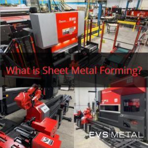
At EVS Metal, these press brake forming capabilities span four facilities with 27 networked press brakes, including robotic automation that supports production of parts ranging from simple brackets to complex multi-bend assemblies with tight tolerances.
When to Use Bending vs. Other Fabrication Methods
Bending serves distinct purposes compared to machining, welding, or other fabrication processes, and understanding when bending provides advantages helps optimize part design and manufacturing approach. The decision often comes down to geometry requirements, production volume, material characteristics, and the structural demands the finished part will face in its application.
Advantages of Bending
Bending creates geometry changes without removing material, which eliminates the waste associated with machining and the material additions required for welded assemblies. This material efficiency means you’re working with the original material properties throughout the entire part rather than introducing weld heat-affected zones or removing structural material through machining operations. For expensive materials or high-volume production, this directly impacts project economics.
Bent parts maintain continuous grain structure through bend transitions, providing better fatigue resistance than welded joints where heat-affected zones create potential failure points. This matters for parts experiencing vibration, cyclic loading, or applications where weld inspection adds cost and complexity. Press brake operations often complete in seconds to minutes depending on part complexity, which is one reason bending remains cost-effective for repeatable geometries. Modern press brake automation extends that advantage by supporting complex multi-bend sequences that turn flat sheets into three-dimensional forms without additional assembly steps—enabling integrated designs that combine multiple functions in single parts rather than assemblies requiring multiple components and fasteners.
Where Bending Must Be Combined with Other Processes
Bending cannot achieve all geometries, and realistic part design recognizes where other processes become necessary. Holes, cutouts, and complex contours require laser cutting or other processes before or after bending. Parts requiring material removal for features like pockets, threads, or precision surfaces need machining operations. Large assemblies may require welding to join bent components into final configurations.
Optimal designs often combine methods—laser cut and bent sheet metal parts with machined inserts or welded structural elements—leveraging each process for its strengths.
Press Brake Bending Processes
Press brakes use punches and dies to create bends through controlled force application. The fundamental principle remains consistent across techniques—applying enough force to permanently deform the material beyond its yield strength while staying below its fracture point. Different bending techniques suit different applications based on tolerance requirements, material properties, and production volume.
Air Bending
Air bending positions material on a V-die while a punch presses into the material without bottoming out against the die. The bend angle is determined by punch depth rather than die shape, which means the same tooling can create various angles by simply adjusting how far the punch travels into the material. This flexibility makes air bending the most common press brake technique for general fabrication work.
Air bending requires less tonnage than other methods, reduces tooling wear, and allows angle adjustments during production—advantages that matter when you’re running mixed-part production rather than dedicated high-volume manufacturing. However, it provides less precise angular control than bottoming, and springback—the tendency of material to partially return toward its original shape after force removal—requires compensation in tooling setup. Air bending suits general-purpose work where tolerances of ±1-2 degrees are acceptable and where tooling flexibility across different angles provides value.
Bottoming
Bottoming forces material into full contact with the die cavity, creating more precise angles than air bending through increased force and fuller die contact that reduce springback variation and improve angular consistency. The technique gets its name from the way the material literally bottoms out against the die profile, taking the exact shape of the tooling.
Bottoming requires more tonnage than air bending and creates sharper stress concentrations at bend lines, potentially affecting material ductility in sensitive applications. It suits parts requiring tighter angular tolerances—typically ±0.5-1 degree—where the additional force and tooling specificity provide value. Most shops reserve bottoming for applications that genuinely need that level of precision rather than applying it universally.
Bumping and Radius Forming
Bumping creates curved sections by making multiple small bends in sequence along a path, approximating smooth radius transitions without specialized rolling equipment. The technique essentially breaks a curve into many tiny straight segments, and when done skillfully, the result appears as a smooth radius rather than a faceted approximation.
Bumping suits prototype work, low-volume production, or parts with varying radii where dedicated tooling investment wouldn’t make sense. The technique requires skilled operators who can visualize the final curve and determine appropriate bend spacing and angles. It provides less precision than dedicated radius dies but offers flexibility for complex geometries that would be difficult or impossible to produce through other bending methods.
Material Considerations for Sheet Metal Forming
Different materials exhibit distinct bending characteristics that affect minimum bend radius, springback behavior, and surface finish quality. Material selection and bending process need to work together rather than being treated as independent decisions.
Material Type and Formability
Low-carbon mild steel provides excellent formability, allows tight bend radii, and exhibits moderate springback that’s predictable and manageable through standard tooling compensation. It suits general-purpose applications where corrosion protection can be provided through powder coating or other finishing. Mild steel also tolerates tighter bend conditions better than harder materials, making it more forgiving during production.
Stainless steel requires greater bending force than mild steel of equivalent thickness, exhibits more springback, and tends to work-harden more aggressively during forming. Grades vary significantly in formability, with 304 and 316 austenitic stainless bending more readily than 400-series ferritic grades. The work-hardening characteristic means stainless steel becomes progressively harder to form as you bend it, which matters for parts with multiple bends where each subsequent bend encounters material that’s already been stressed. Surface finish also requires more attention with stainless since tooling marks that would disappear under powder coat on mild steel remain visible on polished stainless surfaces.
Aluminum allows tight bend radii in annealed tempers but can crack when bent to small radii in harder tempers like 5052-H32 or 6061-T6, making temper selection critical for bendability. Aluminum exhibits significant springback requiring compensation, and surface finish concerns matter more than with steel due to visible marking from tooling contact. The material is also less forgiving of design mistakes—where mild steel might deform plastically, aluminum in harder tempers will simply crack if you exceed its forming limits.
Copper and brass provide excellent formability when annealed but work-harden quickly during forming operations. These materials suit decorative applications where appearance matters, but they require careful handling to avoid surface damage from tooling contact.
Material Thickness and Bend Radius
Material thickness directly affects minimum achievable bend radius, with thicker materials requiring larger bend radii to avoid cracking, fracturing, or excessive stress concentration at bend lines. General guidelines suggest minimum inside bend radius of 1x material thickness for soft materials like annealed aluminum or copper, increasing to 1.5-2x thickness for harder materials or tight-tolerance applications. However, specific material grades, grain direction, and temper significantly affect these relationships.
The physics behind this relationship comes down to how much the outer surface of the material has to stretch around the bend. Tighter radius means more stretching, and at some point you exceed the material’s ductility and it cracks. Designs should specify bend radii considering material properties rather than arbitrary geometry—sharp bends that look clean in CAD may crack during production if material capabilities are exceeded.
Grain Direction and Bending
Sheet metal rolling creates directional grain structure that affects bending behavior. Bending perpendicular to grain direction (across the grain) creates higher crack risk than bending parallel to grain, particularly for materials with poor cross-grain ductility.
Design specifications should note grain direction requirements when bend orientation affects part integrity. For parts with bends in multiple directions, material selection should account for cross-grain bending capabilities rather than assuming the material will perform identically regardless of grain orientation.
Design Guidelines for Bendable Parts
Successful bent part design requires understanding how features interact with bending operations and how geometry affects manufacturability. Engineers addressing design for manufacturability in sheet metal should consider bending constraints during initial design rather than discovering limitations after tooling investment.
Bend Relief and Stress Concentration
Bends terminating at part edges or intersecting other features create stress concentrations that can tear material or create quality issues during forming. Bend reliefs—small notches or holes at bend termination points—allow material to deform without tearing by providing a controlled weak point that prevents stress concentration from creating uncontrolled tears. Relief requirements depend on material thickness, ductility, and bend angle.
Designs should include appropriate reliefs at bend terminations, particularly where bends meet cutouts or part edges at angles other than 90 degrees. The geometry gets complicated when bends intersect at angles because the material has to flow in multiple directions simultaneously, and without adequate relief the material will tear at the intersection point. Getting relief geometry right during design costs nothing; fixing torn parts during production costs everything.
Hole and Feature Proximity to Bends
Holes, slots, or cutouts located too close to bend lines can distort during forming or create cracking at feature edges. A general guideline suggests minimum distance from hole edge to bend line should equal material thickness plus bend radius, though specific applications may require greater clearance. The distortion happens because the material flows during bending, and holes near the bend line interrupt that material flow in ways that create stress concentrations and dimensional changes.
Features requiring precision location should be positioned away from bend zones where material flow and springback create dimensional uncertainty. Features requiring tight positional tolerances may need machining after bending or relocation to flat sections of parts where laser cutting can achieve the required precision.
Bend Sequence and Tooling Access
Parts with multiple bends require consideration of bend sequence—the order in which bends are created—because previously formed bends can interfere with tooling access for subsequent operations. A part might look perfectly feasible in CAD but become impossible to produce if there’s no viable bend sequence that allows tooling to reach all the bends.
Complex parts benefit from design review with fabricators during development because what appears feasible in CAD may require custom tooling, multiple setups, or geometry modifications for efficient production. Early collaboration identifies these issues when design changes cost nothing more than CAD time rather than after tooling has been built.
Tolerance Considerations
Press brake bending achieves different tolerances than machining, and applying machining tolerances to bent features creates specifications that either can’t be met or require expensive secondary operations to achieve. Angular tolerances of ±0.5-2 degrees are typical depending on process selection and material properties. Linear dimensions across bends accumulate variation from springback compensation, material thickness variation, and bend radius uncertainty.
Specifications should reflect achievable bending tolerances rather than defaulting to machining tolerances. Tight tolerances in metal fabrication on bent features may require secondary operations or alternative fabrication approaches. Critical dimensions should be positioned in flat sections of parts where laser cutting or machining can achieve tighter control.
Common Bending Design Mistakes
Several recurring design issues complicate bending operations or increase costs unnecessarily. Understanding common sheet metal fabrication challenges helps designers avoid issues before production.
Specifying Unachievable Bend Radii
Inside bend radii smaller than material thickness often crack during production, especially with harder materials or across-grain orientation. Material and thickness selection should align with required bend geometry rather than forcing tight radii beyond material limits.
Ignoring Springback
Materials spring back toward their original shape after bending force removal. Designs assuming 90-degree bends without accounting for springback create parts that measure 92 or 93 degrees when removed from the press. Fabricators compensate through tooling angles and process selection, but extreme springback situations may require material changes or geometry modifications.
Inadequate Bend Relief
Missing or undersized bend reliefs cause material tearing or distortion at bend terminations. Relief requirements increase with material thickness and decrease with material ductility. Including adequate bend relief during design costs nothing; fixing torn parts during production costs time and money.
Holes Too Close to Bend Lines
Holes positioned near bends distort into oval shapes or crack at edges. Moving holes farther from bend lines during design prevents problems that are expensive or impossible to fix during production.
Applying Machining Tolerances to Bent Features
Bent features cannot achieve machining tolerances economically. Designs should specify achievable tolerances or identify critical features requiring secondary operations rather than assigning blanket tolerances that don’t match process capabilities.
Complex Bend Sequences Without Tooling Consideration
Parts with many bends in multiple directions may require custom tooling, special fixtures, or multiple setups. Design review during development identifies these situations when geometry changes are inexpensive. A skilled fabricator can often suggest minor geometry changes that eliminate custom tooling requirements without affecting part function.
Press Brake Bending Services and Capabilities
For production programs where repeatability matters across multiple part runs, automated press brake environments help reduce setup variation and improve consistency. EVS Metal’s 27 networked press brakes across facilities in Pennsylvania, Texas, New Jersey, and New Hampshire support that type of repeatable production, including robotic multi-bend sequences and offline programming for faster setup transitions. The networking matters because programs developed at one facility transfer to equivalent machines at other locations.
European-style Amada tooling provides precision, extended tool life, and efficient setup changes supporting both prototype flexibility and production efficiency. Offline programming through BendCAD software allows program development concurrent with other operations, minimizing machine downtime. This combination of equipment capability, automation, and programming infrastructure supports production of parts ranging from simple brackets through complex multi-bend chassis and electronics enclosures requiring tight tolerances and consistent quality across production volumes.
Sheet metal forming integrates with EVS Metal’s laser cutting, machining, welding, finishing, and assembly capabilities, supporting complete part fabrication through single-source manufacturing.
Frequently Asked Questions: Sheet Metal Bending
What is the minimum bend radius for sheet metal?
Minimum bend radius depends on material type, thickness, grain direction, and temper. As a starting point, soft materials often bend to 1x material thickness, while harder materials may require 1.5-2x thickness. Specific applications should reference material datasheets or consult with fabricators during design.
How does material thickness affect bending?
Thicker materials require larger bend radii to avoid cracking, need more forming force, and exhibit greater springback. Thickness also limits minimum flange lengths and affects tooling selection for complex parts.
Can you bend stainless steel the same as mild steel?
Stainless steel requires more force than mild steel of equivalent thickness, exhibits greater springback, and work-hardens more aggressively during forming. These factors affect tooling selection, bend sequencing, and springback compensation but do not prevent stainless bending.
What causes cracking during bending?
Cracking results from exceeding material ductility through too-tight bend radius, bending across grain direction in materials with poor cross-grain formability, work hardening from previous forming operations, or material defects. Proper material selection, grain orientation, and bend radius prevent most cracking issues.
How do you calculate bend allowance?
Bend allowance accounts for material stretching around bend radius, affecting flat pattern dimensions before bending. Most CAD systems and press brake controllers include bend allowance calculations based on material thickness, bend radius, and bend angle. Empirical testing with specific material and tooling combinations typically provides the most accurate results.
What tolerance can press brake bending achieve?
Angular tolerances typically range from ±0.5 to ±2 degrees depending on bending process, material properties, and part complexity. Linear tolerances across bends accumulate variation from multiple sources. Critical dimensions requiring tight tolerances should be positioned in flat sections accessible to laser cutting or machining.
How does grain direction affect bending?
Bending perpendicular to grain direction (across the grain) creates higher crack risk than bending parallel to grain. Materials with significant grain directionality should orient bends parallel to grain when possible or select grades with better cross-grain ductility for parts requiring bends in multiple directions.
Ready to Discuss Bending Requirements?
Because bending performance depends heavily on material selection, geometry, and downstream fabrication requirements, early manufacturability review often prevents costly revisions later in production. EVS Metal provides precision sheet metal bending and forming for parts ranging from simple brackets to complex multi-bend assemblies. Our engineering teams can review designs for manufacturability, identify potential bending challenges, and recommend modifications optimizing parts for production. Request a quote or call (973) 839-4432 to discuss bending capabilities and design guidelines for your next project.